Description
The Rotation webservice returns orthogonal triplets of seismic waveform data that have been rotated into specified coordinate systems.
Overview of service
The Rotation webservice returns orthogonal triplets of seismic waveform data that have been rotated into specified coordinate systems.
Detailed description of service
Two dimensional rotation
The rotation service uses the following transformation matrix to change the output vectors for 2-D horizontal transformations


where :
- N , and E represent data from the original (horizontal) orientations
- R,and T represent the Radial and Transverse components.
- α is the azimuth measured clockwise from north
Three dimensional rotation
The rotation service uses the following transformation matrix to change the output vectors

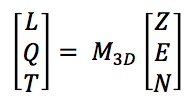
where :
ba is the backazimuth measured clockwise from north
- i is the angle of incidence, measured from vertical
- Z , E , and N represents the 3 seismograms with original orientations
- L, Q, and T represent the three seismograms that are output as below.
- L – Aligned in direction of P wave propagation
- Q – Aligned in the direction of the SV phase movement
- T – Aligned in the direction of the SH phase movement
When original horizontal orientations are at arbitrary angles (but still orthogonal), instead of the initial channel descriptors xxE and xxN, expect xx2 and xx1. The rotation angle would be adjusted accordingly.
Reference: Plešinger, A., M. Hellweg and D. Seidl, Interactive high-resolution polarization analysis of broadband seismograms. J. Geophysics, 59, p. 129-139, 1986.
Rotations
These rotations are available: zne,zrt,lqt
Rotation into ZNE
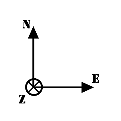
To rotate to a ZNE (Vertical, North, East) system, simply specify components=ZNE.
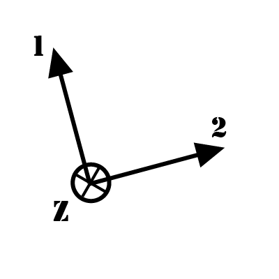 ⇒
⇒ 
Rotation into ZRT
To rotate into ZRT (Vertical, Radial, Transverse) system, specify components=ZRT. This can also be used to rotate into arbitrary azimuths.
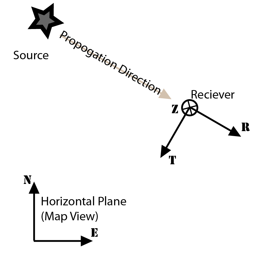
Depicted azimuth of approx 110° …or, a backazimuth of approx 290°
Rotation into LQT
To rotate into LQT (Latitudinal, SV direction, SH direction), specify components=LQT , incidence=<degrees>, and either azimuth=<degrees> or backazimuth=<degrees>
a three channel system with orientations Z12 or ZNE can be rotated into LQT by specifying both the angle of incidence and either an azimuth or backazimuth.
The illustrations depict the rotated components for a query:
...&components=LQT&backazimuth=280&incidence=60
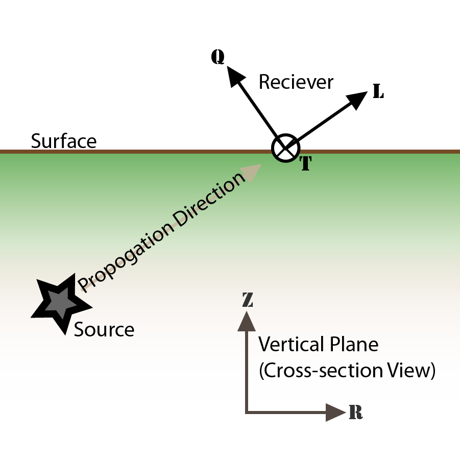
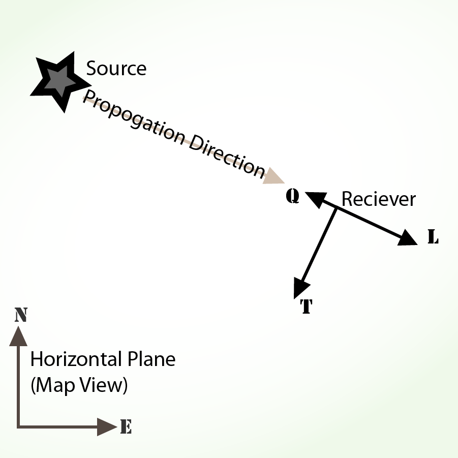
Depicted azimuth of approx 100°
…or, backazimuth of approx 280° Depicted incidence of approx 60°
The L component will be oriented in a direction radially away from the source, aligned with the incident seismic ray. The Q component is in the negative-radial direction, at right angles to the L component. This orientation corresponds to the direction an SV wave would travel. The T component remains parallel to the surface, but at right angles to the plane formed by the Q and T components.
If the resulting data is to be rotated into the L Q T system, then L will be aligned in the direction of incident seismic ray; T remains unchanged (SH component), and Q will be orthogonal to both, in the +Z direction (same as SV componetnt).
Output
Output can either be a plot or a zip file of separate data files (one for each selected component) along with a metadata.properties file, which contains details about the transformation
Specifying a subset of coordinates to be returned
Subsets of any coordinate systems may be selected.
For example: ZNE, NE, ZE, E.
Subsets may not be mixed.
For example, the following are illegal: NRT, ZQT
Components order affects plots.
For example: ZRT and RTZ will perform identical rotational operations, but if output=plot the plot images will have different trace orderings.
metadata.properties file
The metadata properties file contains additional information describing the transformation that has occurred, including:
- source channels that were used
- orientations of the source channels, given as:
- dip (degrees below horizontal)
- azimuth (degrees clockwise from north)
- orientations of the output channels
- units of the output data (for example M/S)
This file is included in the downloaded .zip file along with the files containing the timeseries data. For SAC data output, the data units and channel orientations are also included in the SAC headers.
About the input parameters
Correcting the trace
The trace may have instrument corrections applied. Any corrections or scaling occurs before the rotation is performed.
By default, when correct= is not specified, the trace is neither instrument corrected nor is it scaled. The units will be in raw counts.
Choosing correct=scale will apply Stage zero scaling, effectively multiplying all values by a constant to get units appropriate to the instrument. However, instrument response is not applied.
Choosing correct=response will cause the instrument response to be applied to the source channels
By default, no filtering is done, and raw counts are used. However, one can apply scaling
Original instrument orientations
| ZNE system | Z12 system | |||||||
|---|---|---|---|---|---|---|---|---|
| If the instrument has horizontal components (nearly) aligned with North and East, they will be labeled N and E accordingly. | Horizontal components with arbitrary orientations have been assigned components of 1 & 2. The third component should still be vertical. | |||||||
 |
 |
|||||||
| ZNE Orientations | Z12 Orientations | |||||||
| Chan | Azimuth | Dip | Chan | Azimuth | Dip | |||
| xxZ | 0° | -90° | xxZ | 0° | -90° | |||
| xxN | 0° | 0° | xx1 | Any | 0° | |||
| xxE | 90° | 0° | xx2 | xx1 ± 90° | 0° | |||
The rotation service requires that the the vertical (Z) component is aligned to within a degree of true vertical. It also requires that the horizontal components be nearly 90° from eachother
Components
One of three component systems may be specified: ZNE, ZRT, LQT.
Examples:
- …components=ZNE…
- …components=ZRT&azimuth=318.0…
- …components=LQT&azimuth=318.0&incidence=40.0…
Also, subsets of any coordinate systems may be selected.
Angles
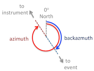
azimuth to which the output coordinate system will be aligned. It is typically chosen to be the direction from a seismic source to the seismic station measured clockwise from north.
backazimuth is typically in the direction from the seismic station towards a seismic source. It is 180° off from the azimuth.
Either azimuth or backazimuth (not both) may be specified when rotating into the ZRT or LQT component systems. For the ZRT system, the R axis will be aligned with the azimuth. For the LQT system, the L and Q axes will be in the vertical plan of the direction of azimuth.
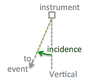
incidence is the angle from vertical at which an incoming ray arrives. A ray arriving from directly below the station would have an incidence of 0°.
The incidence is only supplied when rotating into the LQT component system. The L axis will be aligned with the angle of incidence.
Incoming rays Wave geometry
Symbols that will be seen in the maps:
⊗ : Directed in or out of the page. (ex. The vertical component in a map view),
Problems with this service?
Please send an email report of which service you were using, your URL query, and any error feedback to:
data-help@earthscope.org
We will address your issue as soon as possible.

